Once, the final design and functions were determined, the mechanism to carry this out was explored. Firstly, a mechanism to store the wire was needed, as well as some form of feedback to reassure the user that the wire has been pulled. Through interviews and discussions with the participant, the feedback system was defined as vibration due to its subtlety yet effectiveness.
For this mechanism, two directions can be distinguished; a completely mechanical solution or an electronic mechanism.
Technical ideation
Requirements
-
The mechanism must translate a pull on the wire to a vibration feedback
-
The mechanism must be able to retract and store the wire (and possibly the ring
-
The mechanism must be as compact as possible to make the design discrete
-
The mechanism must be simple to avoid vulnerabilities or malfunctions
In the development process of the mechanism, the below-listed requirements were used to make decisions:
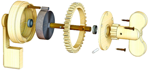
The first idea for a mechanical mechanism makes use of a wind-up mechanism. A simple design of a wind-up mechanism is shown in the picture. Via a winder, kinetic energy is converted to potential energy, which is stored in the spring. If the winder is released, the potential energy will be converted to kinetic energy.
This kinetic energy can be used to initiate a vibration. This can be done by, for example, sliding something over a rough surface. Instead of using a classic winder for the bracelet, the rope can be used as an input for the original kinetic energy. If applied to the bracelet concept, it would work as shown below.
Mechanical Solution
The disk will vibrate when the wire is released instead of pulled. A solution that instantly sends feedback via a vibration could be developed using a spool with flaps attached to it, leaving out the spring and using the direct energy from the pulling to create the vibration.
For the electronic mechanism, the system will make use of an Arduino, vibration motor and a button in combination with a mechanical part. The sketch below visualizes how these parts can trigger a vibration as a result of the wire being pulled.
The wire is stored on a spool that automatically retracts the wire. When the button that is attached to the gear rack is pressed,the wire can be pulled out without triggering the Arduino. When the button is released, the gear rack will click on the spool gear, resulting in a trigger when this spool is twisted. Of course, the choice for an electronic system would make the mechanism susceptible to water, and complicate the systems possible malfunctions. However, an advantage is that the code needed is extremely simple, giving this machine a high probability of working.
Electronic Solution
In this design, the user would get immediate feedback. It is a really simple design and can be made extremely compact. The only thing that would still need to be added is a torsion spring so that the coil returns to its “default” state again.
Choosing a mechanical solution would result in a device that does not need any charging, and consists of a simple mechanism, thereby making malfunctions rare. However, it will be hard to design a small-sized working mechanical vibration motor.

Thus, for the prototype, the electronic solution was chosen for the sake of reliability and the possibility of realisation. The assembly and realisation would require some coding, soldering and assembling.
The system was required to be as slim as possible, which is why a smaller Arduino was ordered. The Arduino Beetle will be capable of translating the button trigger to vibration feedback. Furthermore, it was decided to use the vibration motor, button sensor and some wires from the electronics kit given to the group at the University of Twente. To fit the electronics in the wristband a housing was modelled and 3d-printed. This housing protects the electronics from small shocks and keeps the components in place.
Furthermore, it was decided to go with a powerbank to power the system. This is mainly a consequence of the little time left to polish the prototype making it difficult to find and implement smaller batteries. The aim of the prototype was to test the function rather than having a fully integrated model. Thus, the main wire pulling function, and ease of use and comfortable wearing, were prioritised. In this way a smaller, more compact prototype was designed by keeping the power source exernally.


